


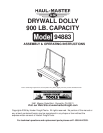

SKU 94883 For technical questions please call 1-800-444-3353. Page 3
9. Do not exceed the product’s maximum load capacity of 900 Lbs. Always make sure the
load is evenly distributed on the Dolly.
10. Only use on a flat surface capable of supporting the Drywall Dolly and its maximum
capacity load of 900 Lbs. It is easy to lose control of the Drywall Dolly if attempting to pull a
load on a sloping or uneven surface.
11. Do not allow children to play on, stand upon or climb on the Drywall Dolly. The Drywall
Dolly is not for carrying people or animals.
12. Always check hardware and parts after assembling. All connections should be tight and
hardware tightened.
13. Always distribute objects in the Drywall Dolly evenly. Uneven weight distribution could
cause tipping. Harbor Freight Tools is not responsible for damage to persons or cargo.
14. Be aware of dymanic loading! Suddenly dropping or bouncing a load on the Drywall Dolly
may create, for a brief instant, an excess load, which may result in damage to the product and/
or personal injury.
Warning: The warnings, cautions, and instructions discussed in this instruction manual cannot
cover all possible conditions and situations that may occur. It must be understood by
the operator that common sense and caution are factors which cannot be built into
this product, but must be supplied by the operator.
Unpacking
When unpacking your Drywall Dolly, check to make sure the following parts are included. If any
parts are missing or broken, please call HARBOR FREIGHT TOOLS at 1-800-444-3353.
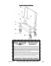
Assembly
Your Drywall Dolly will require complete assembly. It is important that you read the entire manual to
become familiar with the product BEFORE you assemble and use the Dolly. Before operating the
Drywall Dolly, be sure that you have all parts described in the Parts List and Assembly Diagram
page 5 of this manual.
1. Set the Caster Base (B) down on your work bench or work surface. Locate both 8” Swivel
Casters (C). The 8” Swivel Casters (C) will be installed on the front (narrow) side of the
Caster Base (B).
2. Set the 8” Swivel Casters (C) so the holes in the plate line up with the holes in the Caster
Base (B). Insert four Bolts (1) up through the plate and Caster Base (B), slide on Washers
(2), and thread on Locknuts (3)-see Assembly Diagram.
3. Install the 8” Rigid Casters (D) on the rear of the Caster Base (B). Set the 8” Rigid
Casters (D) so the holes in the plate line up with the holes in the Caster Base (B). Insert four
Bolts (1) up through the plate and Caster Base (B), slide on Washers (2), and thread on
Locknuts (3)-see Assembly Diagram.
4. Set the ends of the down tubes on Handle (A) into the fittings on the Caster Base (B)-see
Assembly Diagram. Insert one Bolt (4) through the down tube of the Handle (A) and through
the fitting. Slide on Washers (5), and thread on Locknuts (6).