


5
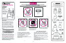
133-7-99 IS2455
678
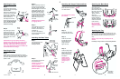
Attaching the Legs
Step 1.
The four legs have a double
button at one end and a single
button beneath it.
With the hub sides facing up,
place the motor housing and
pivot housing on the floor.
Position legs so their single
buttons also face up.
Insert legs into the motor
housing and pivot housing as
shown. The double buttons
must fit into the channels
inside the housings.
Step 2.
Push each leg in until the
double button snaps into
the hole at the end of the
channel. Then swing the
legs outward until the single
button snaps into its notch,
as shown.
Button
in hole
Notch
CHECK that the legs are properly attached by
twisting them in the housings. They should resist
twisting. If a leg twists and buttons come out of
their holes, insert leg into the housing again. Be
sure to align BOTH double buttons with BOTH sets
of channels inside the housings.
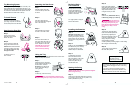
Step 2.
Begin by inserting a screw all
the way into the small hole on
one foot. Position the foot as
shown at right, so the text and
viewing hole are not on the
short side of tube near the
wire end. Then use viewing
hole to line up the end of the
screw with the hole in the tube.
Tighten the screw securely.
Repeat above steps for the
other feet.
CHECK that feet are secure
by wiggling the feet.
Step 3.
Push a plastic tip onto all four
of the feet. Tap leg tips on
the floor to be sure they are
completely on.
The hole in the plastic tip
permits future tightening of the
screw if needed.
Text and
viewing hole
Wire
end
Short side
of tube
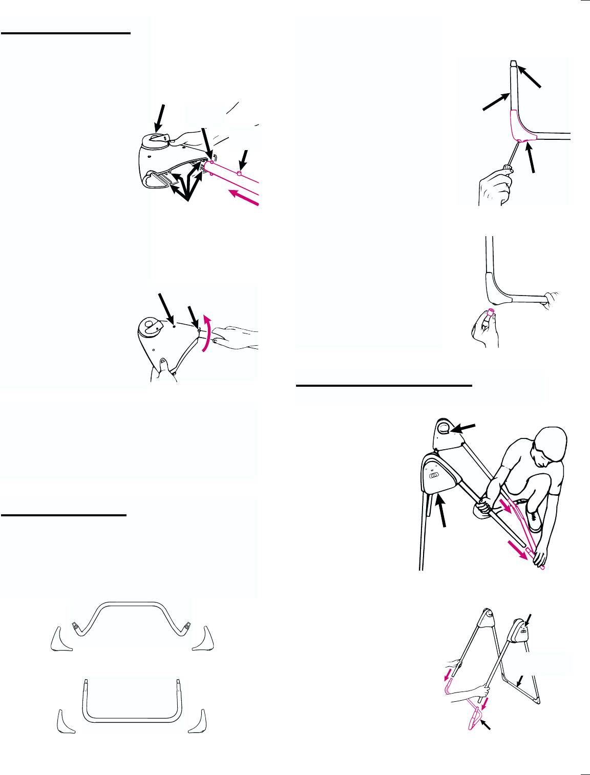
Attaching the Base Tubes
Step 1.
Push the legs firmly onto
the rear base tube
exactly as shown.
Step 2.
Push the other two legs onto
the front base tube.
CHECK that all tubes are
securely attached.
CHECK that the parts of the
frame are assembled in the
positions shown.
Motor
housing
(switch
side)
PUSH
Straight rear
base tube
Bent front base tube
PUSH
Switch
side of
motor
housing
Bracket hole
points toward
rear of swing
OVER
A
A
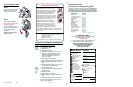
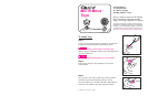
Attaching the Hanger Tubes and Seat
Step 1.
Move seat back fully forward
onto seat armrests.
The seat back must overlap
the armrests.
OVER
A
A
Seat back
Armrest
Working behind the
seat, snap the four
pins in the ends of the
plastic back brace into
the holes in the hanger
tubes. The word
REAR should be
facing you.
Slide adjustment wire
through openings in
seat back, then insert
ends into back brace
holes as shown.
Be sure the back
brace is securely
attached by pulling
on it.
Attaching the Back Brace
Double
button
Single
button
PUSH
Channels
Hub
Step 2.
Slide hanger tubes into
armrests of seat as shown.
Step 3.
Insert two pin screws
through seat armrests
into the holes in the
hanger tubes and
tighten securely.
Step 4.
Insert the hanger tubes
into the hubs as shown.
Metal buttons should
pop out and lock upon
full insertion.
CHECK that the
hanger tubes are
secure in hubs by
pulling firmly on
them.
Attaching the Feet
Step 1.
Identify the front and rear base tubes from pictures
below. The feet to use with each tube can be identified
by the text FRONT BOTTOM or REAR BOTTOM
printed on them.
Front base
tube
Front foot
Rear foot
Rear base
tube
Attaching the Tray
Push sleeve
all the way
into armrest
Place one hand on the armrest and slide the tray onto
the hanger tube with other hand. Push sleeve of tray all
the way into the armrest of the seat until you hear it
snap.
Sleeve on tray must snap completely into the
armrest.
Pull firmly on tray to be sure it is securely attached.