


7
REPAIR INSTRUCTION - GP6124 & GP6128
To Check Valves
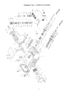
Loosen plugs (56) and take out complete valve (51) with a slide hammer (provided with pump). With a bent
piece of wire, take out o-rings (56A) located between the suction and discharge valves. To dismantle the
valves, carefully tap the valve plate (51B) with a bolt until the valve seat (51A) is pushed out of the spacer
pipe (51D). Check the sealing surfaces and replace all worn parts. Check the o-rings.
When reinstalling the valve, particular care must be taken so that the o-rings sit properly in their fittings in the
valve casing. Tighten the plugs (56) to 160 ft.-lbs..
To Check Seals and Plunger Pipe
Loosen nuts (49A) and remove the pump head. Separate the plunger connection (36) from the crosshead
assembly (25) by means of two open-end wrenches (size 22mm and 27mm). Pull seal sleeves (40) out of their
fittings in the crankcase (1). Take seal case (41) out of seal sleeve (40). Examine plunger (37), guide ring/v-
sleeve (44) and seals (42, 43, 45). Check o-rings (41A and 41C) and support rings (41B and 41D). Replace
worn parts. Grease seals with Silicone before reinstalling. Replace plunger (37) and tighten to 355 in.-lbs.
IMPORTANT: Do not loosen the three plunger screws (36) before the valve casing (50) has been
removed; otherwise, the tension screw (38 for GP6128) or plunger (37 for GP6124) could hit
against the spacer pipe (51D) when the pump is being turned.
For the GP6128, the seal unit (43, 44, 44A) is loaded by spring (42). Seal life can be increased if the loading
allows for a little leakage. This assists lubrication and keeps the seals cool. It is therefore not necessary to
replace the seals before the leakage becomes too heavy and causes output and operating pressure to drop.
When reassembling, tighten plunger (37) to 33 ft.-lbs.
Check o-rings on seal case (41). Clean surfaces of seal sleeves in gear box and sealing surfaces of valve
casing. Push valve casing carefully onto o-rings of seal case and centering studs (49C). Tighten nuts (49A) to
103 ft.-lbs.
To Disassemble Gear End
Take out plunger and seal sleeves as described above. Drain oil. After removing the circlip ring (33B), pry
out seal retainer (33) with a screw driver. Check seals (32, 32A, 33A) and surfaces of crosshead. Remove
crankcase cover (4). Loosen inner hexagon screws on the connecting rods (24) and push connecting rod
halves as far into the crosshead guide as possible.
IMPORTANT: Connecting rods are marked for identification. Do no twist con rod halves. Con rod is to be
reinstalled in the same position on shaft journals. Check surfaces of connecting rod and crankshaft (22).
Take out bearing cover to one side and push out crankshaft taking particular care that the connecting rod does
not get bent.
IMPORTANT:Seal (32A) must always be installed so that the seal lip on the inside diameter faces
the oil.
Reassemble in reverse order: Regulate axial bearing clearance - minimum 0.1mm, maximum 0.15mm - by
means of fitting disc (20A). Shaft should turn easily with little clearance. Tighten inner hexagon screws (10)
to 355 in.-lbs.
IMPORTANT: Connecting rod has to be able to be slightly moved sidewise at the stroke journals.
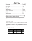
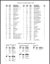
Position Item# Description Torque Amount
10 13133 Inner Hexagon Screw 355 in.-lbs.
36 13219 Plunger Connection 33 ft.-lbs.
38 07131 Tensioning Screw 355 in.-lbs.
49A 13160 Nut, Valve Casing 103 ft.-lbs.
56 13371 Tensioning Plug 160 ft.-lbs.
GP6124 & GP6128 TORQUE SPECIFICATIONS