


Power Supplies Affected
SLS-24-072T
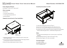
What’s Included
• Part K Cover
• Four Self-tapping Screws M3x6 mm
• Instruction Manual
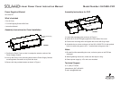
Assembly Instructions for Cover Installation
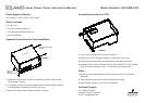
Power Supply Chassis
Part K Cover
Self-tapping screws (4 qty)
M3x6 mm
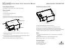
FIGURE 1
1. Position the Part K Cover so that it overlaps the exterior surface of the
Power Supply Chassis.
2. Line up the Part K Cover mounting holes with the Power Supply Chassis
mounting holes. Be careful not to pinch the wires.
3. Secure with the provided screws as shown in Figure 1.
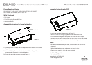
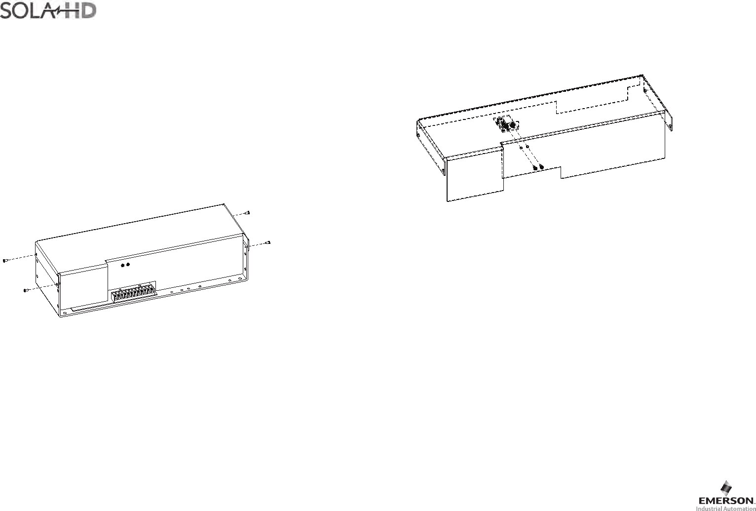
Assembly Instructions for OVP
Part K Cover
FIGURE 2
SLO-12-00-TB
1. Locate the mounting holes as shown in Figure 2.
2. Attach SLO-12-000-TB tightly against the inner side of the cover.
3. Position the mounting holes and tighten the screws with 8 kg torque.
4. Assemble the two wires coming out of the SLO-12-000-TB. On the terminal
block, the white wire goes to the “+” and the black wire goes to the “-”.
Notes
1. Be careful while assembling the cover, so that no parts on the PCB are
damaged.
2. When tightening the screws, make sure the torque is 8 kg.
3. Derate power supply by 15% with cover installed.
Technical Support
U.S.: (800) 377-4384
International: (847) 268-6651
E-mail: tech@solahd.com
Linear Power Cover Instruction Manual Model Number: SLCASK-CVR
Part Number: A272-116 Rev 2
September 22, 2008