


6
Level
Installation, operation & maintenance instructions
IP152, Rev A
D
April 2012
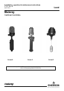
Series B & X
Installation Instructions
When installing, using or maintaining external chambers supplied compliant with the Pressure Equipment Directive,
refer also to the Safety Information (leaflet No. IP152/SI) supplied with the product for further details.
Installation shall be carried out by suitably trained personnel in accordance with applicable codes of practice.
1. Remove all sealing tapes, tie strings and packing from the control prior to installation.
2. Mount the control on the inlet and outlet connections, ensuring that the central line axis of the control is vertical to the
eye. Use suitable process connection gaskets and seals as dictated by the application.
3. Check bolt torques on process and switch head flange bolts are in accordance with torques shown on page 12.
Note
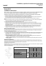
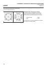
i) A 50mm weld bead or label on the chamber indicates the highest operating level of the control. Switch point adjustment
of 94mm is provided on multi-switch models only and is measured down from this level.
ii) Allow at least 200mm above the control for removal of cover.
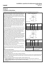
3. Remove switch head cover to reveal terminal block(s) to which electrical connections are to be made.
Flameproof models: Locate and slacken off M5 socket head safety grub screw on side of cover adjacent to base joint.
Place a bar across the top of the cover, locating in the castellations. The cover can now be unscrewed from the base
using the bar as a lever.
Weatherproof models: The cover can be removed by unscrewing the single hexagon nut at the crown of the cover.
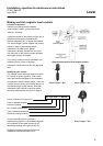
4. Connect electrical wiring via the conduit entries using a suitable cable gland. Note that the base of the enclosure is
rotatable on the pressure tube to allow the most convenient orientation of the conduit entry.
Refer to wiring notes on page 4.
On models with flameproof enclosures type ★7★ the switch mechanism may be raised on the pressure tube to ease access
to the terminal block. Ensure that the switch mechanism is re-positioned to its lowest position (i.e. sitting on the limit tube
around the pressure tube) after wiring.
5. Switch point adjustments may now be made if necessary. See below.
6. The lugs of the tab washer directly underneath the base must now be bent over to locate on the most appropriate flats of
the hexagon union. This prevents further rotation of the switch head, and is particularly important as it will prevent
rotation when the cover is removed or re-fitted.
7. Check the cover seals are present and in good condition, and then replace the cover.
(i) Before energizing flameproof / Type ★7★ models, ensure the cover locking safety grub screw is replaced and
tightened. Do not energize if the cover locking safety grub screw is missing.
(ii) Before energizing weatherproof / Type ★4★ models, ensure the weatherproofing fibre sealing washer at the crown
nut is in place.
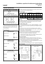
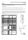
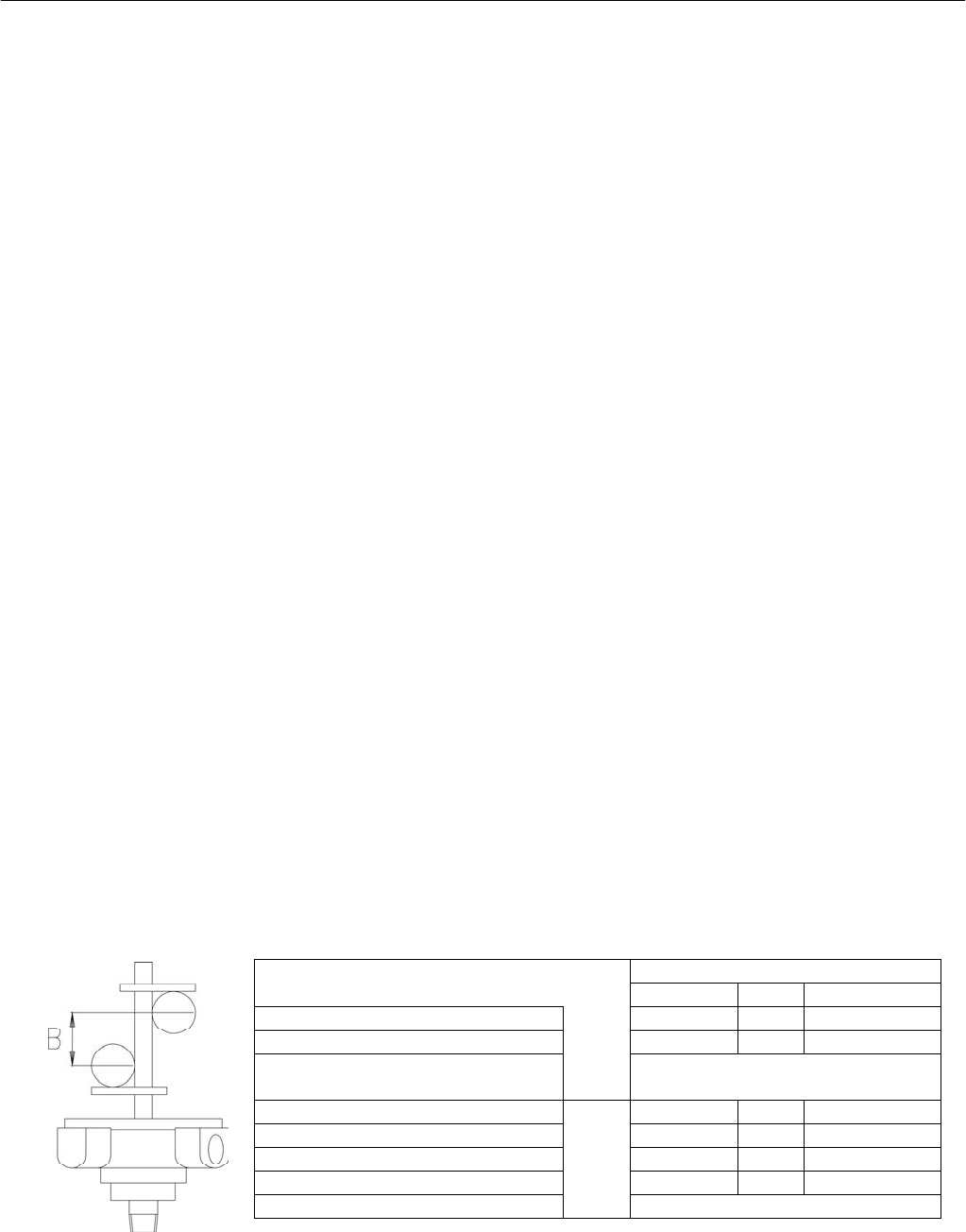
Switching Point Adjustment
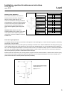
Each switch mechanism is mounted on a bracket, which is secured on the pressure tube by a locking screw and lock nut.
These can be loosened, allowing the bracket to be adjusted up or down as required. Always ensure that the small pressure
plate between the locking screw and the pressure tube is in place before
re-tightening the locking screw nut.
Important note: Switches cannot be adjusted outside of the range set by the stops on the pressure tube. Displacer operated
control type ★★17D are single switch models with the switching point factory set.
There is no site adjustment.
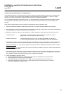
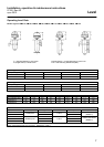
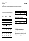
Enclosure Type Sw
itch Mechanism Type
D4, P4, X4 H4 D8, P8, X8, H8
Max. No. Switches R7A
R7I
R4N
1 1 1
Sw. Adjustment ‘B’ mm 7 7 7
Max. Wet
switching
differential
Type 11F, 12F, 13F, 14F : 20mm
Type 17D : See table above (D-C)
Max. No. Switches
S7A
S7I
S4N
4 4 2
Sw. Adjustment ‘B’ mm 94 94 94
Min. Sw Crs ‘B’ mm 94 94 94
Max. Sw Crs ‘B’ mm 7 0 56
Max. Wet switching differential Type 11F, 12F, 13F, 14F : 120mm