


Eskimo Ice Installation Manual - Self-Contained System INSTALLATION PROCEDURES
L-2448A ENGLISH 3
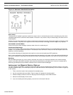
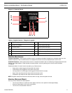
CONSTANT PRESSURE VALVE (CPV)
The CPV is used as the expansion valve of the refrigerant system. It allows high-pressure liquid to become low-pressure liquid
and start the refrigeration process. The simple and reliable CPV provides a constant system pressure over a wide range of
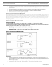
ambient and seawater temperatures. The valve pressure is set at the factory and should not require any field adjustments. On
the rare occasion that an adjustment is necessary, the system must be correctly charged and operating for at least 20 minutes
at an ice-making temperature before any adjustments are made. Recommended pressure is 6 to 7.5 PSI (6.8 PSI is ideal) as
determined by an accurate gauge capable of reading low-pressures. Misadjustment of the valve can cause reduced ice
production, damage to components, and voiding of the warranty. If under warranty, call for authorization before adjusting CPV,
otherwise warranty will be voided.
INSTALLATION PROCEDURES
This section covers the installation procedures for your ice-making system. Read the manual completely before attempting
to install any equipment.
CHOOSING THE CORRECT EQUIPMENT VOLTAGE
Know the frequency and voltage provided where your ice-making system will be used and select the appropriate 60 Hz or 50 Hz
model. Do not operate a 60Hz unit on 50Hz power or a 50Hz unit on 60Hz power, as this will cause damage and void the
warranty.
The voltage rating of a unit is a nominal rating. The voltage in a given location may be higher or lower by as much as 10% and
the system will still operate correctly. For example, in a 60 Hz environment you may see 110 VAC to 120 VAC, or 208 VAC to
240 VAC. In a 50 Hz environment common voltages range from 220 VAC to 240 VAC.
INSTALLING THE UNIT
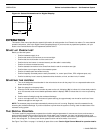
SELECTING THE SITE
Never install the unit in the bow of the boat. Dometic ice-making units are designed to be installed in any convenient location
on the transom, in the aft, or in a machinery space that does not require ignition protection that is as far aft of midship as
possible. The unit can be located in living areas if necessary. Some considerations:
• This equipment is not ignition protected per CFR 183.410 and may not be installed in areas that may be
exposed to flammable gas.
• The unit will produce condensation, so the drip pan is necessary.
• The unit is water cooled and does not need direct ventallation, but do not install in a sealed space.
• The space around the unit may be insulated to reduce noise if necessary.
Site Location Check List
• Location is aft of midship. Never install the unit in the bow of the boat.
• Location is not exposed to flammable gas.
• Location provides adequate space for access to refrigerant, seawater, and electrical connections.
• Location provides accessibility for service and maintenance.
• Location is away from direct spray, from engine air intakes, and from water washdown.
• Mounting space is a flat, horizontal surface.
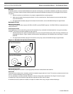
MOUNTING THE UNIT
1. Do not remove any covers, caps, or fittings that may expose any wiring or refrigerant until you are ready for those
steps of the installation.
2. On a flat, horizontal surface, orient the unit so the refrigerant, seawater, and electrical connections are accessible.
For the EI600D and EI500D - Use screws or bolts through the holes in the four corners of the pan to secure it. You can
remove and turn the pan to better orient the drain stub.
For the EI250D - Use the 4 provided hold-down clips to secure it.
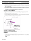
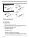
3. The auger has an elbow where the ice exits. The elbow rotates 360 degrees to let the ice-discharge hose go in any
direction toward the ice box. Make sure the elbow is oriented upward so water can re-enter the auger barrel instead of
flowing to the ice box. For the EI250D, the elbow is the same as above, but if the ice-discharge hose needs to go in a
direction other than through the factory hole in the front cover, you will have to drill a hole for the discharge hose in the
appropriate location on any of the other 3 sides or top. Be sure to remove that cover panel from the unit before drilling.