


Thank you for purchasing the MCA3545 Bi-Amplifier. It was designed and built to provide years of high quality sound reproduction
when used in active 2-way loudspeakers for music playback, computer sound systems, and home theater applications. The ampli-
fier includes features like user selectable high pass and low pass filters, independent high and low frequency level controls, rugged
independent LM3886TF output devices, and comprehensive internal protection against shorted speaker loads, thermal faults, and
overload conditions.
• 24dB/octavehighpassandlowpasslters
• Balancedandunbalancedlinelevelinput
• Thermal,overloadandfuseprotectioncircuitry
• AutoOn/Offstand-bycircuit
• Operateson115Vof230V
Features:
• Userselectablehighandlowfrequencycrossoverpoints
• IndependentLM3886TFoutputdevices
• Masterlevelcontrol
• Independenthighandlowlevelcontrols
• Switchable3dBlowfrequencyboost
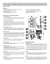
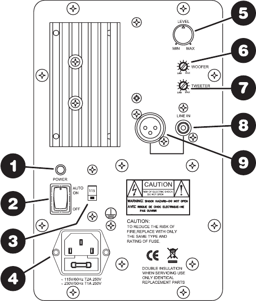
Front Panel Controls/Connections
1. Power Status LED
ThepowerLEDilluminateswhenthepowerswitchisintheON
position.After20minutesofnosignaltheunitwillgointostand-
bymodeandtheLEDwilldim.
2. Power Switch (Off/Auto On)
TheamplierismanuallyturnedONorOFFviathisswitch.When
instand-bymode,(nosignalpresent)thecurrentdrawandheat
generatedisverylow,thereforeitcanbeleftintheONposition
indenitely.Theunitwillgointostand-bymodeifnosignalis
presentfor20minutes.
3. Voltage Selector Switch
Thisswitchallowstheusertoselect115Vor230Voperation.The
unitissetatthefactoryfor115Voperation.Whenoperatingat230V
besuretochangethefusetoaslowblow1A,250Vtypefuse.
4. IEC Power Jack
ThisunitfeaturesagroundedIECtypepowerjack.Thisallows
theusertochangethepowercorddependingonthecountryand
voltageused.TheIECjackalsohousesthefuseholderwhich
uses5mmx20mm,slowblow250Vtypefuse.Theunitissetat
thefactoryfor115VoperationandissuppliedwithaUSAtype
powercordanda2Aslowblow250Vfuse.
5. Level Control
Thisisthe“master”levelcontrolthatadjuststheoveralloutputlevel
(bothhighandlowlevelsimultaneously)oftheamplier.
6. Woofer Control
Independentlyadjustslowfrequencyoutputlevel,tothewoofer
only.Adjustmentrangeis0~+5dB.
7. Tweeter Control
Independentlyadjustshighfrequencyoutputlevel,tothetweeter
only.Adjustmentrangeis0~+3dB.
NOTE:Independentwooferandtweeteradjustmentsallowprecise
speakercomponentbalancing,compensatingfordifferentlevels
inprogrammaterialandvaryingroomacoustics.
8. RCA Input
RCAconnectionacceptsstandard1Vp-plinelevelsignal.This
istheunbalancedlinelevelinputforconnectiontostandard
consumergradeequipmentandaudioequipmentcommonlyused
inhomeapplications
9. XLR Input
Thisisthebalancedlinelevelinputforconnectiontomixing
consolesandotherprofessionaltypeaudioequipmentcommonly
usedinstudioapplications
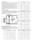
Output Connections
Speaker Outputs
Therearetwosetsofspeakeroutputslocatedontherear(PC
boardside)oftheampliermodule.Eachcolorcodedred(+)
andblack(-).Theblackornegativewirefeaturesa.110"push
onconnectorandtheredorpositivewireusesa.187"pushon
connector.Outputconnectionslistedbelowassumeyouarefacing
therearoftheampliermodule(PCboardside),withthepower
transformerlocatedtotheleft.Loadsoneachoutputleadmust
haveanominalimpedanceof8ohmorhigher.
Tweeter
Thisoutputconnectionislocatedonthefarrightsideofthemain
amplierPCboard.Notetheredandblackleadsareconnected
tocorrespondingtabsonthePCboardlabeledT+andT-.
Woofer
Thisoutputconnectionislocatedtowardsthemiddleleftsideof
themainamplierPCboard,approximately2-1/2"fromtheleft
edgeoftheboard.Notetheredandblackleadsareconnectedto
correspondingtabsonthePCboardlabeledW+andW-.
(2)