


Operating Instructions
DMX Control Mode
The ST-4000RGB™ can be operated from a DMX controller. This control mode environment gives
the user the greatest flexibility when it comes to customizing or creating a show by enabling the
control of each individual trait of the fixture and each fixture independently.
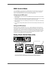
Configuring for DMX control
1. Connect the (male) 3 pin connector side of the DMX cable to the output (female) 3 pin connector
of the controller.
2. Connect the end of the cable coming from the controller which will have a (female) 3 pin connector
to the input connector of the next fixture consisting of a (male) 3 pin connector.
3. Then, proceed to connect from the DMX output as stated above to the DMX input of the following
fixture and so on.
4. If you need help setting the DMX address read the section titled “Setting the DMX address” in this
Chapter.
Setting the DMX address
Each fixture requires a "start address" from 1 to 511. A fixture requiring one or more channels for
control begins to read the data on the channel indicated by the start address. For example, a fixture
that occupies or uses 7 channels of DMX and was addressed to start on DMX channel 100, would
read data from channels: 100, 101, 102, 103, 104, 105 and 106. Choose start addresses so that the
channels used do not overlap and notate the start address selected for future reference. If this is
your first time, read the DMX Primer in the Appendix Section.
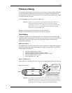
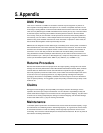
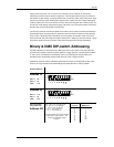
Daisy Chain (Serial Data Link)
DMX Input
Use certified DMX XLR cable
DMX Out
p
ut
DMX:001
DMX:013
DMX:007
5
4
3
2
6
7
8
9
10
7
6
5
4
3
2
1
1
7
6
5
4
3
2
1
8
9
10
8
9
10
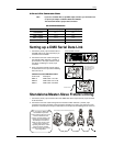
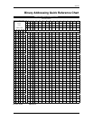
Visit the section titled; Binary & DMX DIP-switch Addressing on page 13 & Binary Addressing Quick
Reference Chart on page 14 to quickly determine the binary DIP-switch settings for addressing.
ST-4000RGB User Manual 11 2008-11-07/11:37