


39 Operation and Maintenance
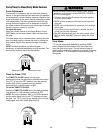
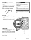
Your gate operator is programmed with self-diagnostic capabilities. The diagnostic LED will flash a number of times then
pause signifying it has found a potential issue. Consult Diagnostic Chart below.
Normal Operation
Stop is not connected.
• Press the RESET button and make sure the STOP LED turns on.
• Check to make sure the jumper wire is connected between the COM and STOP input
on the control board. Stop is a normally closed input.
Battery voltage is below the recommended operating level.
• Battery may not be properly charged. Disconnect all batteries and make sure AC
power or solar power is connected. Verify AC power outlet.
• Verify that the battery fuses are intact and not blown. Replace blown fuses with same
type and rating.
• Batteries are no longer capable of holding a charge due to age or excessive depleting
of the battery. Replace the batteries (see accessories page). Dispose of old batteries
properly.
Gate 1 has encountered an obstruction or the arm is disconnected.
• Make sure the path of the gate is clear and the gate moves freely.
• Incorrect or poor connection to Gate 1 arm. Check the green and white wires on the
motor arm to make sure connections are correct and secure.
• Bad arm or control board. Press the LEARN LIMITS button and press the GATE 1
buttons to move the arm. If the arm does not move continuously, disconnect arm from
Gate 1 and connect the arm to the Gate 2 connector and repeat the attempt to move
the arm. If the arm does not move continuously on either Gate 1 or 2, replace the arm.
Gate 1 has encountered an obstruction.
• Make sure the path of the gate is clear and the gate moves freely.
• If there is no obstruction the force adjustment is set too low. Increase the force setting
and verify that the gate moves without reversing and will reverse if an obstruction is
encountered.
Gate 2 has encountered an obstruction or the arm is disconnected.
• Make sure the path of the gate is clear and the gate moves freely.
• Incorrect or poor connection to Gate 2 arm. Check the green and white wires on the
motor arm to make sure connections are correct and secure.
• Bad arm or control board. Press the LEARN LIMITS button and press the GATE 2
buttons to move the arm. If the arm does not move continuously, disconnect arm from
Gate 2 and connect the arm to the Gate 1 connector and repeat the attempt to move
the arm. If the arm does not move continuously on either Gate 1 or 2, replace the arm.
Gate 2 has encountered an obstruction.
• Make sure the path of the gate is clear and the gate moves freely.
• If there is no obstruction the force adjustment is set too low. Increase the force setting
and verify that the gate moves without reversing and will reverse if an obstruction is
encountered.
Potential RAM, Flash, or EEPROM failure.
• Turn power off and on.
• If problem does not resolve itself by turning power off and on, replace the control
board.
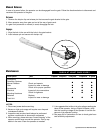
Force Reversal Gate 1
RPM Reversal Gate 1
or Arm Disconnected
Low Battery Voltage
STOP not connected
Power ON
2 FLASHES
3 FLASHES
5 FLASHES
6 FLASHES
1 FLASH
RPM Reversal Gate 2
or Arm Disconnected
7 FLASHES
Force Reversal Gate 2
8 FLASHES
Potential chip failure
9-11 FLASHES
Low Battery
Capacity
4 FLASHES
Diagnostic Chart