


Adjusting the quick release mechanism
The wheel hub is clamped in place by the force of the quick release cam pushing against
one dropout and pulling the tension adjusting nut, by way of the skewer, against the
other dropout. The amount of clamping force is controlled by the tension adjusting nut.
Turning the tension adjusting nut clockwise while keeping the cam lever from rotating
increases clamping force; turning it counterclockwise while keeping the cam lever from
rotating reduces clamping force. Less than half a turn of the tension adjusting nut can
make the difference between safe clamping force and unsafe clamping force.
Front Wheel Secondary Retention Devices
All 2007 and newer BOB Strollers have front forks which utilize secondary wheel retention
devices designed to help keep the wheel from disengaging if the quick release is
incorrectly adjusted. Secondary retention devices are not a substitute for correct quick
release adjustment. The secondary retention devices on your stroller are the integral
type that is formed into the outer faces of the front fork dropouts.
WARNING: Do not remove or disable secondary retention devices. As its name
implies, they serve as a back-up for a critical adjustment. If the quick release is
not adjusted correctly, the secondary retention devices can reduce the risk of the
wheel disengaging from the fork. Removing or disabling the secondary retention
devices may also void the warranty.
Secondary retention devices are not a substitute for correct quick release
adjustment. Failure to properly adjust the quick release mechanism can cause
the wheel to wobble or disengage, which could cause you to lose control and fall,
resulting in serious injury or death.
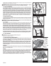
Installing a Quick Release Front Wheel:
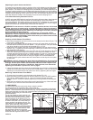
a. Move the quick release cam lever so that it curves away from the wheel (Fig. 9). This
is the FULLY OPEN position.
b. Insert the wheel between the fork blades so that the axle seats firmly at the top of
the slots that are at the tips of the fork blades the fork dropouts. The quick release
cam lever should be on the left side of the stroller (Fig. 11 & 12).
c. Holding the quick release cam lever in the OPEN position with your right hand as
shown in Fig. 11, tighten the tension adjusting nut with your left hand until it is finger
tight against the fork dropout.
d. While pushing the wheel firmly to the top of the slots in the fork dropouts, and at the
same time centering the wheel rim in the fork, move the quick release cam lever
upwards and swing it into the FULLY CLOSED position (Fig. 9 & 12). The lever should
now be parallel to the fork blade and curved toward the wheel. To apply enough
clamping force, you should have to wrap your fingers around the fork blade for
leverage, and the quick release cam lever should leave a clear imprint in the palm
of your hand.
WARNING: Securely clamping the wheel takes considerable force. If you can fully
close the quick release without wrapping your fingers around the fork blade for
leverage, and the quick release cam lever does not leave a clear imprint in the
palm of your hand, the tension is insufficient. Open the lever; turn the tension
adjusting nut clockwise a quarter turn; then try again.
e. If the quick release cam lever cannot be pushed all the way to the fully closed position
parallel to the fork blade, return the lever to the OPEN position. Then turn the tension
adjusting nut counterclockwise one-quarter turn and try tightening the lever again.
Removing a Quick Release Front Wheel:
a.
To remove the front wheel, open the brake quick release (Fig. 10).
b. Move the wheels quick-release lever from the locked or FULLY CLOSED position
to the FULLY OPEN position (Fig. 9). Your front fork has integral secondary
retention devices. Loosen the tension adjusting nut enough to allow removing the
wheel.
c. Raise the front wheel a few inches off the ground and tap the top of the wheel with
the palm of your hand to knock the wheel out of the front fork.
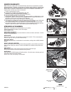
7. HAND BRAKE:
The hand brake may be used to help slow or stop the stroller.
The hand brake is not a parking brake. (See section 8)
After installing the front wheel, the brake caliper will need to be placed in the closed
position. Close the brake quick release lever (Fig. 10) by squeezing the brake pads
against the wheel with one hand, then rotate the brake quick release lever in the counter
clockwise direction with your other hand until it
points downward.
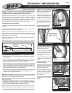
For the hand brake to work correctly, it is
critical that it be adjusted properly. Squeeze
the brake lever and verify that the brake
pads contact the rim as shown in Fig. 15.
If they are misaligned, use a 10mm wrench
to loosen brake pad nuts, slide pads into
correct position and tighten securely. The
cable tension is pre-adjusted at the factory
yet the brake cable will need periodic
adjustment (as the cable stretches slightly
and the black cable housing compresses
over time). To adjust cable tension, there
are two barrel adjusters in the brake
assembly (Fig.10 & 13). To tighten the cable,
loosen the lock ring and turn the barrel
OMS03A
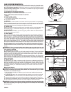
Cross Tube Hole
Metal Tab Hole
Fig. 8 Fender Installation
Fabric
Screw
Hole
Brake
Mounting
Plate Hole
Fender Hole
Screw
Fender
Fig. 10 Caliper Brake Anatomy
Brake
Quick
Release
Lever
Brake Pad
Brake
Pad Nut
Brake Body
Barrel
Adjuster
Brake & Fender
Mounting Screw
10 mm Nut
Lock
Nut
Fig. 9 Front Wheel Quick Release Anatomy.
(rotate to
adjust
clamping
force)
FULLY
OPEN
FULLY
CLOSED
Tension
Adjusting
Nut
Quick Release
Cam Lever
Conical Springs
Fender Screws
Fabric Screw
Fabric Screw
Fig. 7 Fender Screws
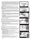
Fig. 11 Front fork dropouts shown
with wheel in position. Adjust nut snug
with Quick Release in open position.
Fork
Blade
Fork
Dropouts
Quick
Release
Cam
Lever
Open
Tension
Adjusting
Nut
P3
Fork
Blade
Quick
Release
Cam Lever
Closed
Fig. 12 Quick Release in the closed
position and parallel to fork blade.