BOB is a company that produces high quality products, which encourage
a healthy, outdoor, car-free life-style. In addition to strollers, we also
make single-wheeled cargo trailers for bicycles. See www.bobgear.com
for our complete line of products. Before attempting to assemble
or use your new stroller, read and understand these operating
instructions completely to insure proper assembly and operation.
If you are unclear on any point, contact your dealer or BOB before
use.
WARNINGS
.
Never leave child unattended in the stroller.
.
Failure to properly assemble or install the quick release wheels on
this stroller may result in the wheels becoming detached while
moving and a subsequent loss of control of the stroller.
.
Always use seat harness to avoid serious injury to child from sliding
or falling out of stroller.
.
Never allow occupants to stand in stroller.
.
The parking brake is not designed as a stopping brake. The brake
should not be used to slow or stop the stroller. The brake is intended
to park the stroller on flat surfaces, not on inclines. Never leave
your children in the stroller unattended with or without the parking
brake set!
.
Do not attach parcels or bags to the handle or frame of stroller
except those recommended by BOB, as stroller can become
unstable and tip over.
.
The maximum load of the stroller is 70 lbs (32 kg). Do not exceed
maximum load (occupant plus luggage weight) as stroller will
become unstable.
.
Do not place sharp objects in the seatback pocket as your child
leans against this and can be injured as a result.
.
When starting out, always make sure the childs hands and feet
are away from wheels.
.
Follow instructions and use care when folding and unfolding stroller
to prevent finger entrapment (see section 13).
.
The stroller is not equipped for use after dark. If you intend to use
at night, we recommend installing a lighting system available through
your local bike shop.
.
We do not recommend wearing roller skates or in-line skates while
pushing stroller.
.
Never run with the stroller in Swivel Mode (see section 6)
.
Do not use stroller on stairs or steep inclines. Stroller can tip over,
resulting in injury.
.
Never pull a loaded stroller backwards up stairs. Doing so could
damage the suspension system leading to frame failure and
serious injury to the user and/or the occupants.
.
Always use Wrist Safety Strap.
BOB IS NOT RESPONSIBLE FOR INJURY, DAMAGE, OR FAILURE
THAT RESULTS FROM OWNERS FAULTY ASSEMBLY OR
MAINTENANCE AFTER SHIPPING.
AGE RECOMMENDATIONS:
It is recommended that your child be a minimum of 6 to 8 weeks old
before riding directly in the stroller seat. Young babies incapable of
holding their head up must be provided additional head and neck
support to ride safely. For jogging and off road use, children should
be at least 6 to 8 months old.
Children develop at different rates. Consult
with your pediatrician regarding the
suitability of the stroller use with your
child.
ASSEMBLY
INSTRUCTIONS:
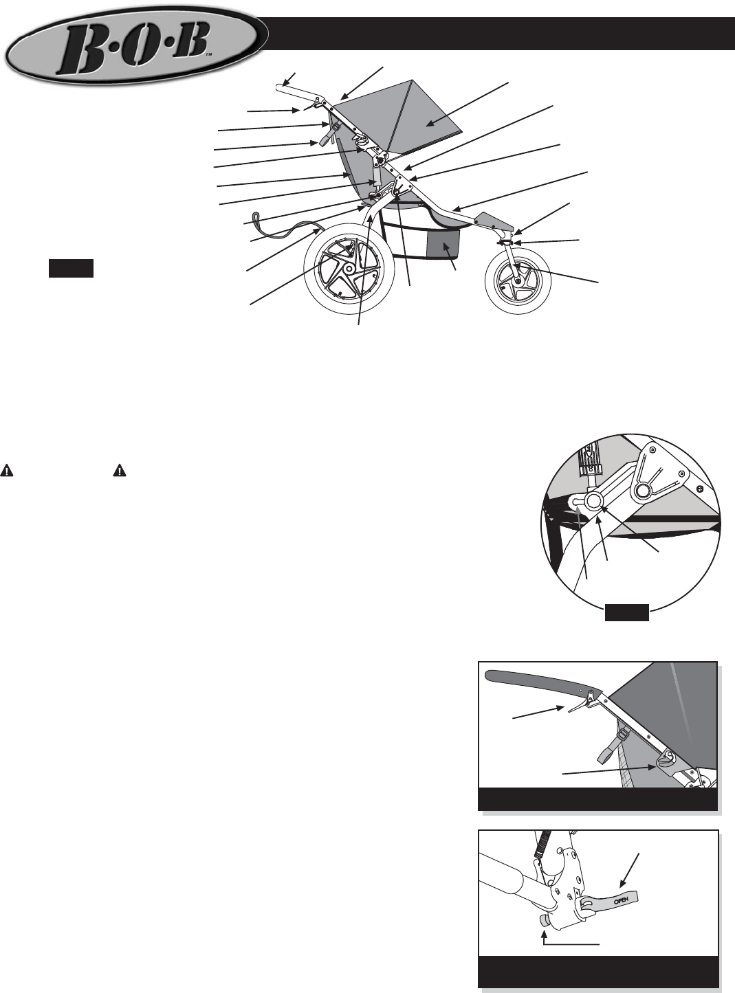
Reference Fig. 1 as it describes
the various parts of the stroller.
1. UNPACK: Remove stroller
and stroller wheels from
packaging. Plastic packaging
material was used to protect the
front fork dropouts, the front
wheel axle quick
release, handlebar
release levers and
the metal shock
brackets. Remove
these plastic pieces.
2. SWINGARM:
Rotate the
swingarm away
from the front of the
stroller until the
shocks engage in
the first position (Fig.
2). Each shock
locking pin will
snap and lock into
position 1.
3. HANDLEBAR:
Rotate the stroller
handlebar up to the
fully open position.
Slider Latches will
lock into place (Fig.
3).
4. REAR WHEEL:
Place the rear wheel quick release lever in the open position, as
shown in Fig. 4. Insert the rear wheels stub axle into the hole in the
rear dropout. If the axle does not slide in easily, loosen the quick
release adjusting
nut (Fig. 4) by hand.
Re-insert the axle
fully into the rear
dropout until the
axle shoulder or
snap ring on the
axle comes in
contact with the
dropout (Fig. 5).
Move the quick
release lever to the
closed position (Fig.
6). The word
CLOSE should be
clearly visible and
the quick release
lever should almost
touch the dropout.
When properly
adjusted, it will
require
considerable torque
(80-105 in-lbs or 9-
12 Nm) to close the
lever. If you do not
feel this resistance
(too loose or too tight), return the quick release lever back to the open
position (Fig. 4), and adjust the adjusting nut (clockwise to tighten,
counterclockwise to loosen). Move the quick release lever to the
closed position (Fig. 6).
NOTE: Follow all instructions exactly. If you are unsure how to operate
the quick release, consult your
dealer or contact BOB.
5. FRONT WHEEL: (Fig. 7)
shows the anatomy of the front
wheel and quick release.
The front forks dropouts are
slotted to receive the front
wheel (Fig. 8). Slide the wheel
into the dropouts so that the
quick release lever is on the
left hand side of the stroller
when the fork is rotated forward
and locked in Jog Mode (see
section 6). Make sure the
wheel is centered in the fork
and that the axle is touching
the top of the drop out slot.
Securely tighten the wheel in
place as follows: With the quick
release lever in the open
position (Fig. 8), tighten the
adjusting nut (clockwise) until
it comes in contact with the
dropout. Move the quick
release lever to the closed
position (Fig. 9). This should
require significant pressure. If
you do not feel significant
resistance, turn the quick
release lever back to the open
position (Fig. 8), and hand
tighten the adjusting nut one or
two turns in the clockwise
direction until snug. Move the
quick release lever toward the
closed position (Fig. 9). The
word CLOSE should be clearly
visible and the quick release
lever should be parallel to the
stroller fork leg. It should require
considerable torque (80-105 in-lbs
or 9-12 Nm) to close the lever when
properly adjusted.
to properly adjust quick release
may result in wheel loss and serious
personal injury. If you are unsure
how to operate the quick release,
consult your dealer or call BOB.
6. SWIVEL LOCKOUT: The
Revolution Stroller can be used in
one of two modes. The stroller can
be used as a swiveling wheel
stroller (Swivel Mode) when the
Lockout Knob is in the unlocked
position (Fig. 10). Or, it can be used
as a fixed wheel stroller (Jog Mode)
when the swivel Lockout Knob is
in the locked position (Fig. 11). To
change from Swivel Mode to Jog
Mode, lift and slide the Lockout
Knob (Fig. 10) up and all the way
to the right. Then release the knob,
and it will snap down. Next, rotate
the fork until the pin engages and
locks the fork in position. You are
now ready to use the stroller in Jog
Mode. To change the stroller back to Swivel Mode, lift the Lockout
Knob and rotate it to the left.
7. TRACKING ADJUSTMENT:
It should be noted that all fixed three wheeled vehicles can be easily
influenced to deviate from a straight path. In some cases strollers can
have or develop a tendency to pull to the right/left due to many different
factors including tire pressure, wheel installation, road conditions and
manufacturing tolerances. If you find your BOB stroller to significantly
track or pull to the left or right while in Jog Mode during use on flat
terrain, follow the sequence of instructions below.
Tracking Adjustment Instructions:
Note: Tracking adjustment can only be performed with the stroller fork
locked out (Jog Mode). Roll test the stroller as described below. It is
recommended you have someone assist with this task in order to
catch and return the stroller. Fig. 12 illustrates the roll test process.
a. Empty the stroller. Do not roll test with a child or any occupant
in the stroller.
b. Find a location on level ground approximately 16 ft. long. It is helpful
to use an existing straight-line as a frame of reference such as the
edge of the sidewalk or a painted line in a playground.
c. Align the stroller so the rear
wheel axles are perpendicular to
the straight line. Push and release
the stroller, trying carefully not to
influence its direction to the left or
right, so it rolls straight down the
test path. This step should be
performed more than once to make
sure the stroller was not biased
left or right by the pushing action.
d. If the stroller consistently pulls
to the left or right when pushed
straight, proceed with the steps
Fig. 1
Anatomy of the
BOB Revolution
Stroller.
Fig. 7
Front wheel Quick Release Anatomy.
Adjusting
Nut
Quick
Release
Lever
Tire/Wheel
Cam
Housing
Handlebar Release Lever
Sun Canopy
Canopy Drawstring
Handlebar
Swing Arm
Shock Absorber
Shock Release Button
Slider Latch
Seat Back Pocket
Seat Recline Adjusters
Wrist Safety Strap
Frame Release Handle
Swing
Arm
Pivot
5 Point
Safety Harness
Foot Well
Low Boy
Cargo
Pouch
Seat Pockets
Rear Canopy Flap
Parking Brake
Fork
Tracking
Adjustment Knob
Swivel Lockout Knob
Fig. 12
Stroller roll test.
16
Stroller pulls
to left
90
o
Wheel axles
perpendicular
to straight line
Stroller pulls
to right
Top View Of Stroller
Position 1
Shock
Release
Button
Position 2
Swingarm in unfolded position
with shock in position 1.
Fig. 2
(800) 893-2447 www.bobgear.com email- info@bobgear.com
Phone: (208) 375-5171 Fax: (208) 375-5172, BOB Trailers, Inc. 5475 Gage St. Boise, Idaho 83706
BOB REVOLUTION OWNERS MANUAL
Fig. 13 Tracking Adjustment.
Tracking
Adjustment
Knob
Fork
Fig. 3 Handlebar in the fully open position.
Handlebar Release
Lever
Slider Latch
Fig. 10 Swivel Lockout -
Unlocked Position (Swivel Mode)
Swivel
Lockout
Knob
(Unlocked
Position)
Fork
Fig. 11 Swivel Lockout -
Locked Position (Jog Mode)
Swivel
Lockout
Knob
(Locked
Position)
Fork
MA0606
Quick Release
Open
Adjusting Nut
Fig. 4 Rear wheel Quick Release with
lever in open position.
Fig. 5 Rear wheel properly installed
(left side shown).
Snap Ring or
Axle Shoulder
Dropout
Insert
Wheel
Fully
Quick
Release
Closed
Fig. 6 Quick release in the
closed position (right side shown).
Fig. 8
Front fork dropouts shown
with wheel in position. Adjust nut snug
with Quick Release in open position.
Fork
Dropouts
Quick
Release
Open
Adjusting
Nut
Fig. 9 Quick Release in closed
position and parallel to fork leg.
Fork
Dropout
Quick
Release
Closed


