


instructions exactly.
If you are unsure
how to operate the
quick release,
consult your dealer
or contact BOB.
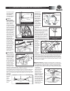
FENDER
INSTALLATION:
Before installing the
front wheel, you will
need to attach the
fender. The two
attachment screws
can be found already
installed on the frame
(Fig. 7). Remove the
two fender mounting
screws. You may
wish to remove a
fabric screw (right or
left) to give better
access to the cross
tube fender screw.
Align the hole in the
metal tab of the
fender with the
threaded hole in the
center of the front
cross tube and
install screw (Fig.
8). Align the hole in
the plastic fender
with the hole in the
brake mounting
plate and install
screw (Fig. 8).
Center fender on
stroller and tighten
both screws.
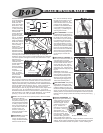
FRONT WHEEL:
(Fig. 9) shows the
anatomy of the front
wheel quick release.
Remove the adjuster
nut and one spring
from the quick
release, and install
the quick release rod
into the wheel axle.
Install the spring
(small end towards
the center of the
wheel) and screw on
the adjuster nut by
turning in a clockwise direction. Tighten the nut only three turns (final
adjustment will be made after the wheel is installed).
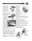
As the strollers tires are wider than the rims, and as the brake pads
are adjusted to the rims, the brake caliper will need to be opened
before mounting or removing the wheel. Open the brake quick release
(Fig. 10) by squeezing the brake pads together with your right hand,
and pulling
down and
then rotating
the brake
quick
release
lever
outward with
your left
hand.
The front forks
dropouts are
slotted to receive
the front wheel
(Fig. 11). Slide
the wheel into
the dropouts so
that the quick
release lever is
on the left hand
side of the
stroller. Make
sure the wheel is
centered in the
frame and that
the axle is
touching the back of the drop out
slot.
Securely tighten the wheel in place
as follows: With the quick release
lever in the open position (Fig. 11),
tighten the adjusting nut
(clockwise) until it comes in contact
with the stroller dropout. Move the
quick release lever to the closed
position (Fig. 12). This should
require significant pressure. If you
do not feel significant resistance,
turn the quick release lever back to
the open
position (Fig.
11), and
hand tighten
the adjusting
nut by one or
two more
turns in the
clockwise
direction.
Move the
quick
release lever
toward the
closed position (Fig. 12). The word CLOSE should be clearly visible
and the quick release lever should be parallel to the stroller frame
tube. It should require considerable pressure (80-105 inch-pounds)
to close the lever when properly adjusted. NOTE: Follow all instructions
exactly. If you are unsure how to operate the quick release, consult
your dealer or call BOB.
PARKING BRAKE: The brake is a parking brake, it prevents the
stroller from moving while loading and unloading it. The parking brake
is not designed as a stopping brake. We do not recommend using
the brake to slow or stop the stroller. The brake is intended to park
the stroller on flat surfaces not on inclines. Never leave your children
in the stroller
unattended with or
without the parking
brake set! After
installing the front
wheel, the brake
caliper will need to be
placed in the closed
position. Close the
brake quick release
(Fig. 10) by squeezing
the brake pads against
the wheel with your
right hand and rotating
the brake quick
release lever in the
counter (over)
(800) 893-2447 www.bobgear.com email- bob@bobgear.com
Phone: (805) 541-2554 Fax: (805) 543-8464, 3641 Sacramento Dr. #3 San Luis Obispo, California 93401
5
6
Fig. 5 Rear wheel installed with
snap ring contacting dropout.
Snap Ring
Dropout
Fig. 6 Quick release in the
closed position.
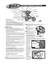
Fig. 10 Caliper Brake Anatomy
Brake
Quick
Release
Lever
Brake Pad
Brake
Pad Nut
Brake Body
Barrel
Adjuster
Brake & Fender
Mounting Screw
10 mm Nut
Lock
Nut
Fender Screws
Fabric Screw
Fabric Screw
Fig. 7 Fender Screws
Cross Tube Hole
Metal Tab Hole
Fig. 8 Fender Installation
Fabric
Screw
Hole
Brake
Mounting
Plate Hole
Fender Hole
Screw
Fender
Quick Release Lever
Cam Housing
RodAdjusting Nut
Conical
Springs
Fig. 9 Front Quick Release Anatomy
Fig. 12 Quick Release in the closed
position and parallel to frame tube.
Fig. 11 Front wheel dropouts
shown with wheel in correct position.
Quick release lever perpendicular
to the dropout.
Dropouts
Fig. 13
Fig. 14
Brake lever in the set position
with button depressed.
Brake lever Lock Ring Barrel Adjuster
Parking Brake Button
Brake Lever
Body
Parking Brake Button
7
MA0207