


11
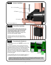
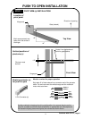
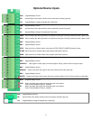
PUSH TO OPEN INSTALLATION
Both measurements are
taken from the center of
the hinge.
11”
6”
Direction of opening
Gate (closed)
Hinge post
Top View
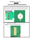
Vertical position of
pivot arm (s)
Pivot arm must
be level
1/2”
Hinge post
Center Line of attachment
point for gate bracket
Front View
PIVOT ARM (s) INSTALLATIONSTEP 1
Location of
pivot point
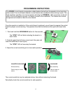
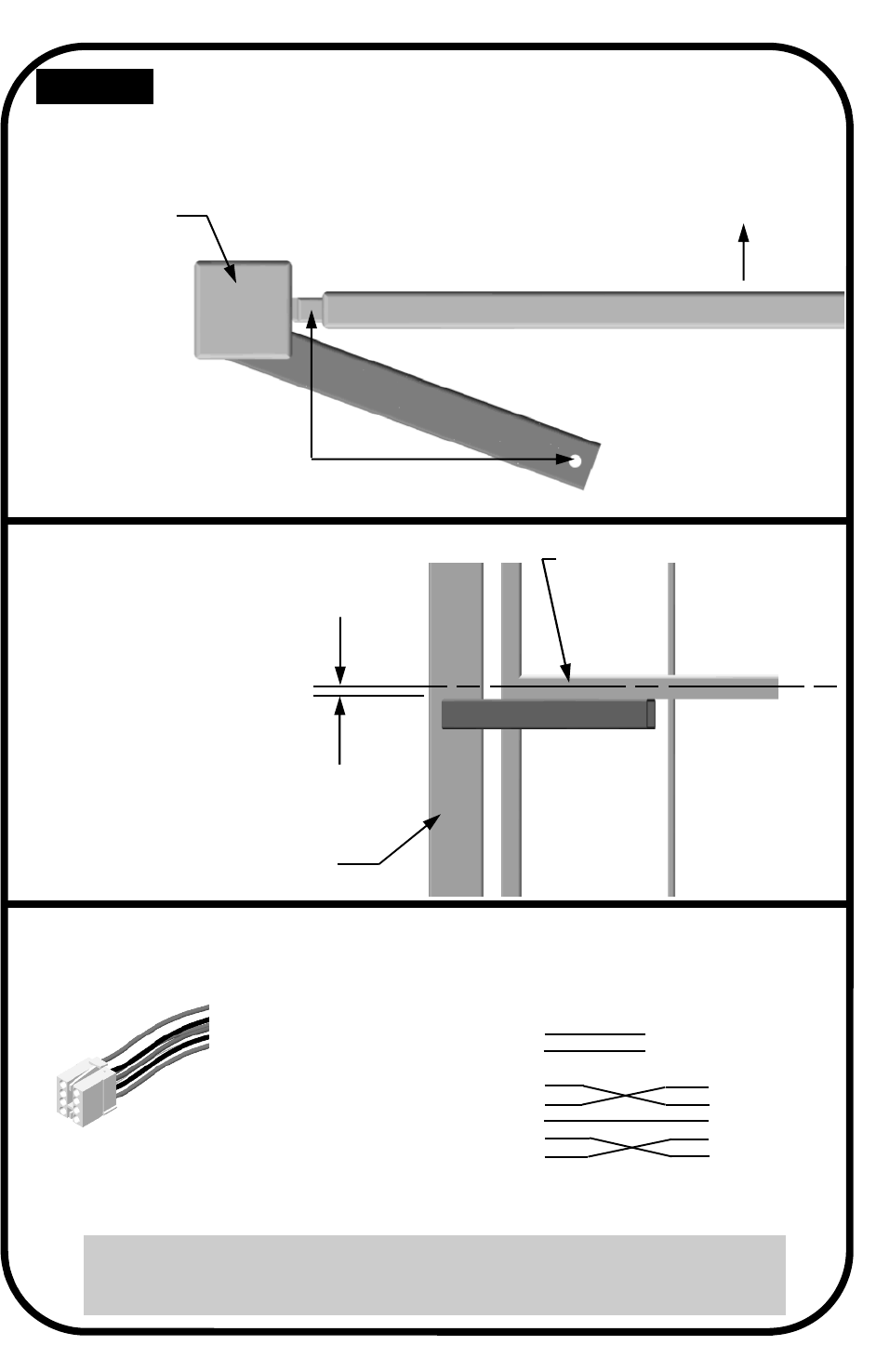
Rewiring actuator (s)
for push to open
Must be re-wired for proper operation
Strip back 6” of black sleeve from connector end of the actuator
cable. Cut and reconnect the white/orange and the red/black
motor wires as shown:
8 Pin Connector (s)
Red
Black
Red
Black
Green
White
Orange
Red
Black
Green
White
Orange
Battery +
Battery -
Continue with STEP 2, Page 8
Another method of changing the wiring configuration is to remove the pins on the
plug with a jeweler's common blade screwdriver or appropriate tool (the staples on
the actuator shipping carton work great) and reinsert as shown above.