


10
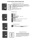
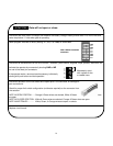
635/636 CONTROL BOARD CONNECTIONS
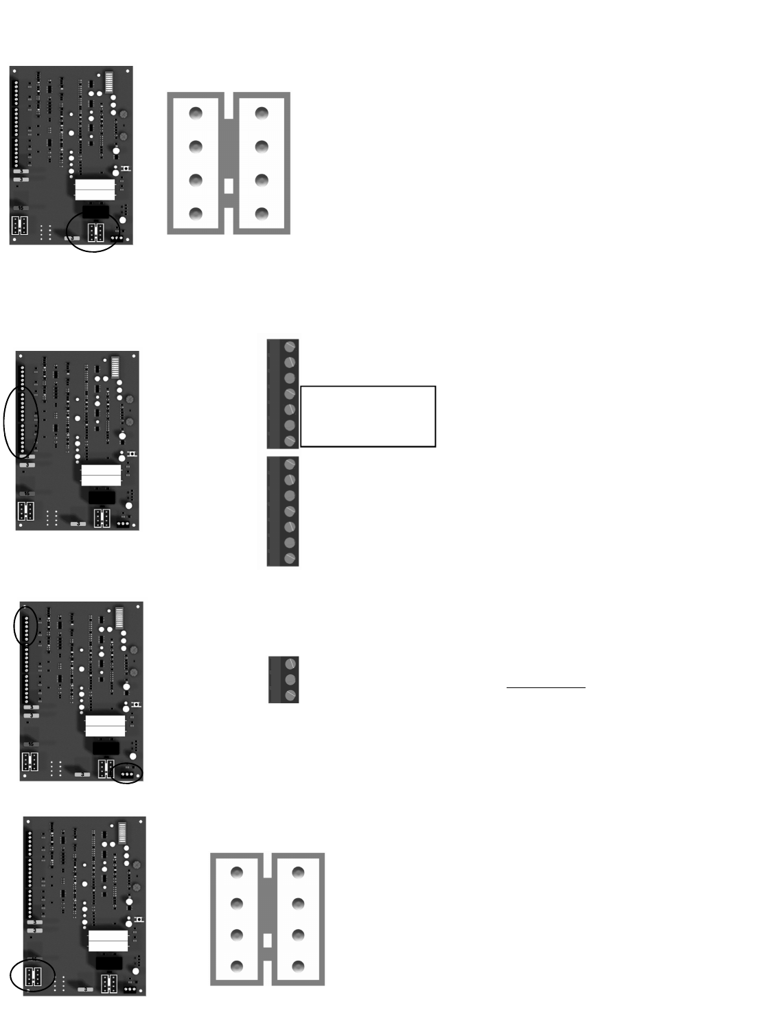
Emergency Bypass Connector
Used when the control board is not functioning. Unplug the
motor harness from the Master (or Slave) Connector and
momentarily insert into the Emergency Bypass Connector to
open the gate. In the event the motor is not disconnected
quickly enough, the blue 15 amp fuse will protect the circuit
board from damage and should be replaced when the
original problem is fixed.
8 Pin White Connector (two on 636 Master & Slave)
7 Pin Black Connectors
1 Edge 1 Input
2 Edge 2 Input
3 Ground
4 Ground
5 Stop Input (N/C)
6 Close Input (N/O)
7 Open Input (N/O)
8 Ground
9 Ground
10 Free Exit Input (Open only for telephone entry, probes, etc.)
11 Ground
12 Under Gate or Shadow Loop Input
13 Ground
14 Safety Loop or Photo Beam Input
3 Pin Black Connectors (3)
GND Ground
INP Input (Activates gate when momentarily connected to ground)
12V +12 Volt Output (For powering options - 3 Amps Max.)
1 ORANGE - Open Limit Input (Normally open unless gate is opened)
2 WHITE - Close Limit Input (Normally open unless gate is closed)
3 BLACK - Motor - Positive during open cycle, Negative during close cycle
4 RED - Motor - Negative during open cycle, Positive during close cycle
5 GREEN - Ground (Limit Switch Common)
6 Ground Not used
7 BLACK - Ground - Battery Negative
8 RED - Battery Positive (+12 VDC)
8
6
4
2
7
5
3
1
MASTER
123
3 Button Control