


Alacritech Scalable Networking Accelerator Hardware Installation Guide (Fiber) 2-1
2 Hardware Installation
2.1 Hardware Installation Overview
Alacritech Accelerators are designed for servers and storage systems on a Gigabit
Ethernet network using TCP/IP. The system they are installed in must have the follow-
ing features:
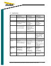
• Supported operating system (see readme on CD for latest OS support)
• One available bus-mastering PCI or PCI-X slot, with 3.3 volt power supplied
for the 1000 Series, and 5 volt power supplied for the 2000 Series Accel-
erators, or PCIe slot for PCIe based Accelerators
• CD-ROM or compatible drive, or network CD drive for software installation
The network should have the following features:
• 1000BASE-SX Gigabit Ethernet using Multimode fiber (62.5/125µm or
50/125µm), with SC connectors for the 1000 Series, and Duplex LC con-
nectors for the 2000 Series Accelerators
Note: The Accelerator is supplied with a dust cover protecting its fiber optic
ports. To prevent dust from collecting on the fiber optic lenses, keep the
dust cover on the ports at all times when they are not in use. Only re-
move the dust cover just before you plug in a connector.
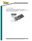
2.2 Installing the Low Profile Bracket (PCI and PCI-X Accelerators Only)
The Accelerator includes a low profile bracket to facilitate installation in a low profile
slot. To install an Accelerator in a low profile PCI slot, the bracket on the rear of the
card will need to be changed with the included low profile bracket.
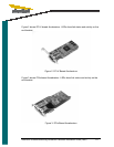
1. Remove the two 4-40 x 3/16 screws on the bottom side of the card.
2. Install the low profile PCI bracket, making sure that the mounting tabs are
on the bottom side of the card and the screws secured from the component
(top) side.
To convert an Accelerator from low profile to standard PCI, the bracket on the rear of
the card will need to be changed to the original bracket.
1. Remove the two 4-40 x 3/16 screws from the topside of the card.
2. Install the standard PCI bracket, making sure that the mounting tabs are on
the top (component) side of the card and the screws secured from the bot-
tom side.