


4
English
Nederlands
FrançaisDeutschEspañol
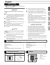
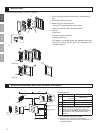
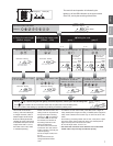
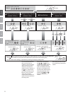
MOUNTING
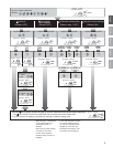
1. Fix the mounting bracket to the back (or surface-mount)
box.
2. Connect the wires to the unit.
3. Mount GT-AC to the front frame.
• Mount GT-AC from behind the front frame.
• Insert the notch into the slots on both sides.
4. Options
a.Rain hood
b.Hooded surface-mount box
c.Surface-mount box
* For details on mounting panels and modules other than
the GT-AC, refer to the GF, GH or GT Installation and
Operation Manual.
3
2
1
4
to GT-AC
to GT-AC
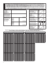
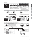
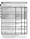
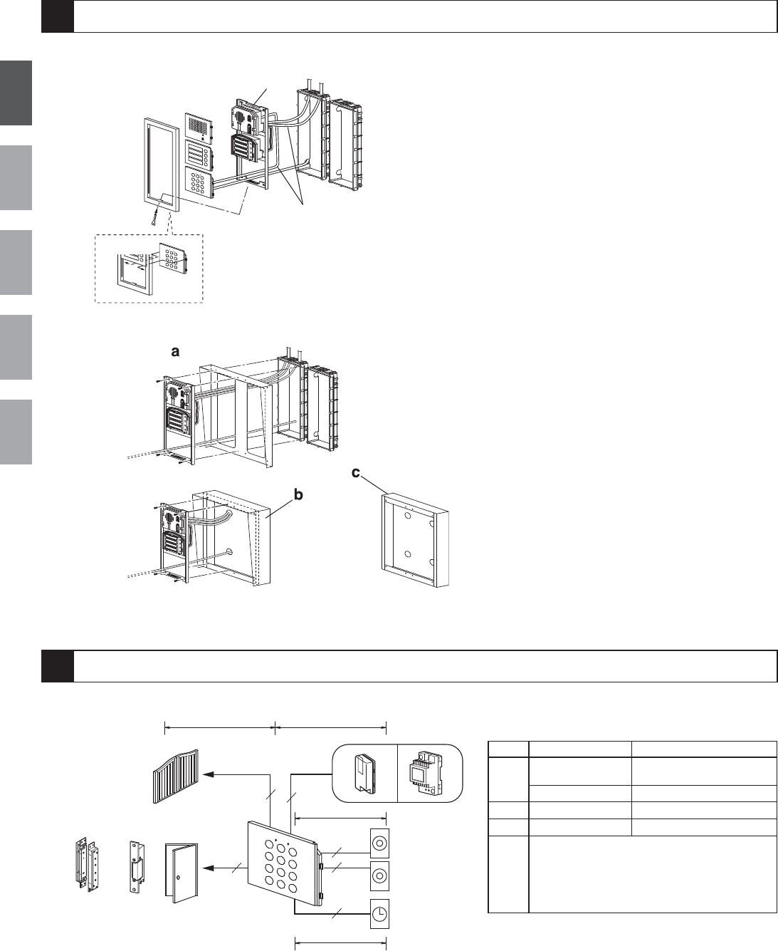
MOUNTING/WIRING METHOD, WIRING DISTANCE
Electric
door strike
Electromagnetic
door lock
Automatic gate
Request to exit/entry
button
Relay
Relay
Request to exit/entry
button
Timer
Power supply
or
C
B
AD
2
2
2
2
2
2
Power supply
diameter 0.65 - 1.0 mm (22-18AWG)
A
AC/DC12 ~ 18V
(Less than)
100m (330')
AC/DC18 ~ 24V
300m (980')
B
-
300m (980')
C
- 300m (980')
D
The connection distance will depend on
the specifications of the electric door strike,
relays or Electromagnetic door lock to be
connected. To determine the operating range,
please refer to the specifications of each
terminal.
(*1) Use a separate power supply for the GT-AC, not
the ones used to power the system.
(*2) Two relays can be activated from GT-AC.
However, only one relay can be activated from a
residential station.
(Wiring distance)
The illustrations below use the GH system.