


8 78-8119-6018-2 Rev C
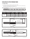
Instructions for Wire Shielded Cable
7.0 Prepare Cable
7.1 Check to be sure cable size fits within kit size range as shown in Table 1.
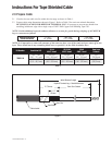
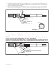
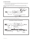
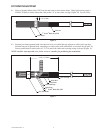
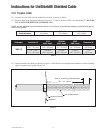
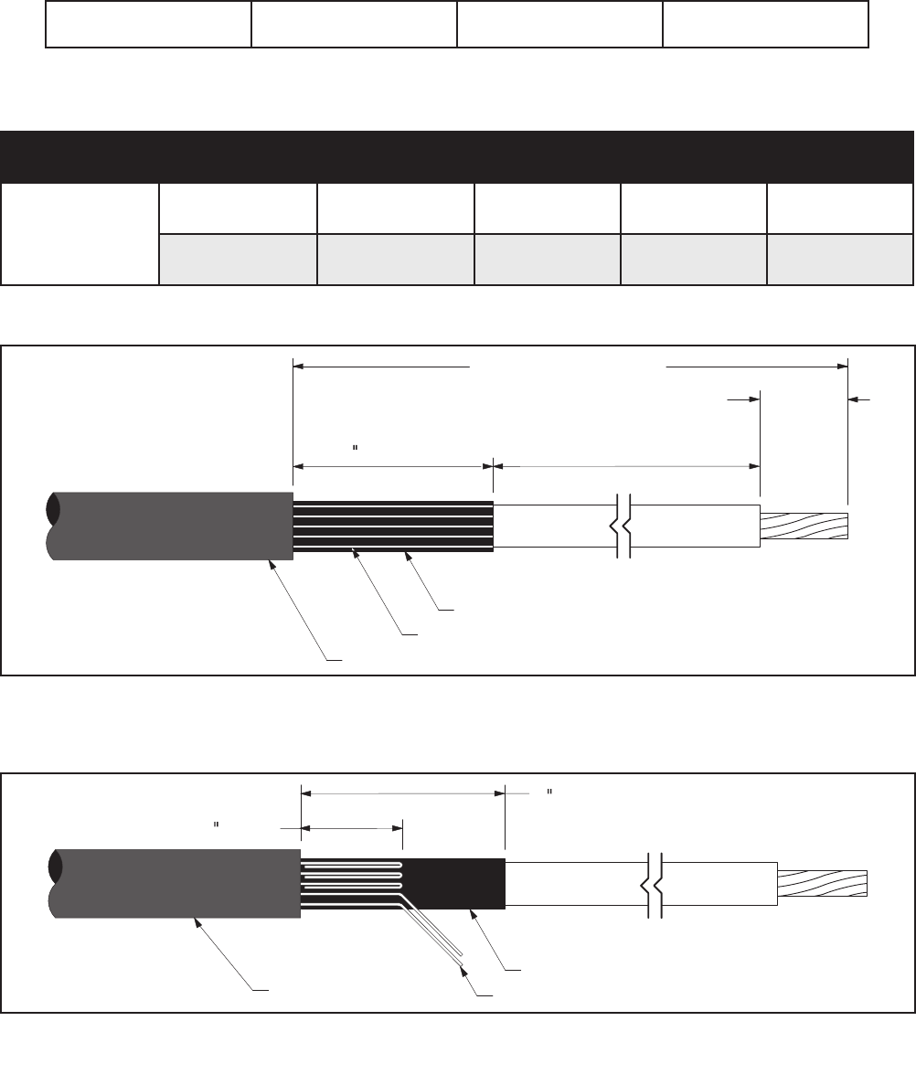
7.2 Prepare cable using dimensions shown in Figure 8 and 9. Refer to Table 3 for semi-con cutback dimension.
BE SURE TO ALLOW FOR DEPTH OF TERMINAL LUG.
NOTE: Provide additional exposed conductor distance to account for growth during crimping of ALUMINUM
lugs or connectors as follows:
Aluminum Connector
Growth Allowance
2 - 350
1/4” (6 mm)
400 - 650
1/2" (13 mm)
750–1000
3/4" (19 mm)
NOTE: It is imperative to remove all remnants of the semi-con layer, even if the semi-con layer comes off as one
layer. There should not be any remaining black areas, or particles, on the cable insulation layer.
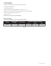
Kit Number Insulation 0.D.
15 kV
AWG / kcmil
25/28 kV
AWG / kcmil
35 kV
AWG / kcmil
Semi-con
Cutback
7685-S-8
1.05" -1.46"
(26,7 - 37,1 mm)
500-700
(240 - 400 mm
2
)
250-500
(125 - 250 mm
2
)
3/0-350
(95 - 150 mm
2
)
13.5"
(342,9 mm)
1.24" - 1.80"
(31,5 - 45,7 mm)
750-1000
(400 - 500 mm
2
)
600-800
(300 - 400 mm
2
)
500-600
(185 - 325 mm
2
)
13.0"
(330,2 mm)
Table 3
Depth Of Terminal Lug + Growth Allowance
3 (76 mm)
Jacket Removal Length
Semi-Con
Shield Wires
Cable Jacket
Semi-Con Cutback
Figure 8
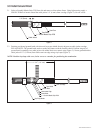
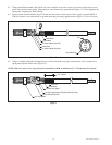
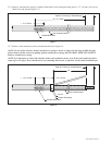
7.3 Bend leading 1 1/2" (38 mm) of exposed shield wires back upon themselves to jacket edge (Figure 9).
3 (76 mm)
1 1/2 (38 mm)
Semi-Con
Shield Wires
Cable Jacket
Figure 9