


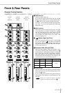
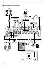

Front & Rear Panels
MG12/4FX
20
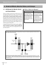
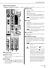
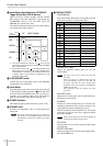
8 Level-Meter Signal Switches (ST-GROUP
Toggle Switch and 2TR IN Switch)
These level-meter switches, together with the channel
PFL switches, select the signal that is sent through the
C-R/PHONES control to the C-R OUT jacks, the
PHONES jack, and the level meter
The following illustration shows how the switch settings
correspond to the signal selection.
*1 If the input channel’s PFL switch is on ( ), then only the
channel’s PFL output it sent to the C-R OUT jacks, PHONES
jacks, and level meter.
*2 If the 2TR IN switch is ON ( ), the signal supplied to the
2TR IN jack is sent to the C-R OUT jacks, PHONE jacks,
and level meter. If the 2TR IN switch is OFF, then the Group
or Stereo signal is sent instead (as determined by the
ST-GROUP toggle switch).
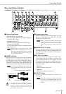
9 C-R/PHONES Control
Controls the level of the signal output to the PHONES
jack and the C-R L and R jacks.
0 Level Meter
This LED display shows the level of the signal selected
by the selection switches described in 8 above (the level
to the C-R OUT and PHONES jacks). The “0” point cor-
responds to the standard output level. The indicator
lights up red when the output hits the clipping level.
A POWER Indicator
This indicator lights up when the mixer’s power is ON.
B PHONES Jack
Connector for headphones. This is a stereo phone-type
output jack.
The signal monitored by these jacks is selected by
the settings of the ST-GROUP toggle switch, the
2TR IN switch, and the PFL switches on the input
channels.
C DIGITAL EFFECT
•PROGRAM Dial
Selects the internal digital effect to be applied. You can
select from 16 effects, as shown in the table.
•PARAMETER Control
Adjusts the parameter (depth, speed, etc.) for the
selected effect.
The mixer saves the last value used with each
effect type.
When you change to a different effect type, the
mixer automatically restores the value that was
previously used with the newly selected effect
(regardless of the current position of the PARAM-
ETER Control knob).
These parameter values are retained even after
power-off.
•AUX PRE Control
Adjust the level of the signal sent from the internal dig-
ital effector to the AUX bus.
• ON Switch
Switches use of the internal effect on or off. The inter-
nal effect is applied only if this switch is turned on. The
switch lights up orange to indicate that it is on.
With the (separately sold) YAMAHA FC5 foot switch
connected, you can use your foot to toggle the digital
effects ON and OFF.
When you turn on the power, the ON switch lights up
and the internal effector becomes active.
• PFL Switch
Set this switch on if you wish to output the effect signal
to the PFL bus.
• EFFECT RTN Fader
Adjusts the signal level from the internal digital effec-
tor to the STEREO bus.
2TR IN
2TR IN
PFL
PFL
GROUP
ST-GROUP
ST
ON
OFF
ON
ON
OFF
OFF
C-R OUT
&
PHONES
Signal
Switch
*1
*2
NOTE
No Program Parameter
1
REVERB HALL 1 REVERB TIME
2
REVERB HALL 2 REVERB TIME
3
REVERB ROOM 1 REVERB TIME
4
REVERB ROOM 2 REVERB TIME
55
55
REVERB STAGE 1 REVERB TIME
66
66
REVERB STAGE 2 REVERB TIME
77
77
REVERB PLATE REVERB TIME
88
88
DRUM AMBIENCE REVERB TIME
9
KARAOKE ECHO DELAY TIME
0
VOCAL ECHO DELAY TIME
A
CHORUS 1 LFO FREQ
B
CHORUS 2 LFO FREQ
CC
CC
FLANGER LFO FREQ
DD
DD
PHASER LFO FREQ
EE
EE
AUTO WAH LFO FREQ
FF
FF
DISTORTION DRIVE
NOTE
NOTE