


Connection Cable and Cable Wiring
Industio CI-134 Series User’s Manual 5-5
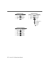
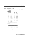
DB-37 Connector Pin Outs
The following lists pin assignment of the Industio CI-134 Series DB37 connector on
the bracket.
For RS-422 Mode
Pin no. Signal Pin no. Signal
1 20 CTS2-(A)
2 TxD2-(A) 21 RxD2-(A)
3 GND/VEE2 22 RTS2-(A)
4 CTS2+(B) 23 RTS2+(B)
5 TxD2+(B) 24 RxD2+(B)
6 CTS3-(A) 25 TxD3-(A)
7 RxD3-(A) 26 GND/VEE3
8 RTS3-(A) 27 CTS3+(B)
9 RTS3+(B) 28 TxD3+(B)
10 RxD3+(B) 29 CTS1-(A)
11 TxD1-(A) 30 RxD1-(A)
12 GND/VEE1 31 RTS1-(A)
13 CTS1+(B) 32 RTS1+(B)
14 TxD1+(B) 33 RxD1+(B)
15 CTS0-(A) 34 TxD0-(A)
16 RxD0-(A) 35 GND/VEE0
17 RTS0-(A) 36 CTS0+(B)
18 RTS0+(B) 37 TxD0+(B)
19 RxD0+(B)
Note: Make shield grounded to connector.
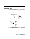
For RS-485 Mode
Pin no. Signal Pin no. Signal
2 Data2-(A) 25 Data3-(A)
3 GND/VEE2 26 GND/VEE3
5 Data2+(B) 28 Data3+(B)
11 Data1-(A) 34 Data0-(A)
12 GND/VEE1 35 GND/VEE0
14 Data1+(B) 37 Data0+(B)
Note: Make shield grounded to connector.