M051-00K63-A032
Life Fitness Upright Exercise Bikes
How To:… INSTALL THE EXTERNAL POWER KIT
Tools Required: 5/16 Nut Driver, T-20 Torx Driver, T-30 Torx Driver, Wire Cutters
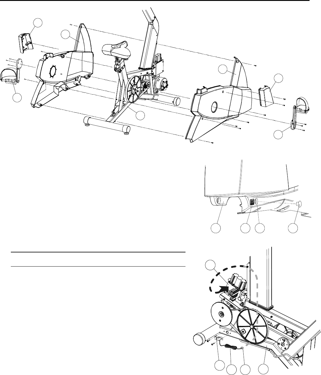
1. Remove the screw securing the RIGHT and LEFT SEAT POST
SHROUDS (A & B) together. Remove the SEAT POST SHROUDS and
set them aside.
2. Remove the three screws securing the USER RIGHT CRANK ARM
AND PEDAL ASSEMBLY (C) to the crank arm mounting plate. Set the
USER RIGHT CRANK ARM AND PEDAL ASSEMBLY aside. Repeat
the procedure for the USER LEFT CRANK ARM AND PEDAL
ASSEMBLY (D).
3. Remove the 10 screws securing the RIGHT and LEFT MAIN
SHROUDS (E & F) together. Remove the user RIGHT and LEFT MAIN
SHROUDS from the FRAME (J).
4. Remove the HOLE PLUG (G) from the lower front of the USER LEFT
MAIN SHROUD (E).
5. Using two supplied screws, attach the BRACKET ASSEMBLY (H) to the
front and user left side of the FRAME (J).
NOTE: THE CABLE (K) SHOULD BE ROUTED TOWARD THE
BOTTOM OF THE UNIT.
6. Route the CABLE (K) under the FRAME (J), around the user right side
of the bike, and to the CONTROLLER BOARD (L) located on the front,
user right side of the FRAME. Plug the 2-PIN (2P) connector into the
available 2-PIN JACK on the CONTROLLER BOARD.
7. Secure the CABLE (K) to the FRAME (J) bottom using a supplied WIRE
TIE. Trim the excess wire tie.
8. Reverse Steps 1-3 to return all SHROUDS and CRANK ARM
ASSEMBLIES to their proper locations.
9. Place the POWER REQUIREMENT STICKER (M) next to the POWER
PLUG ACCESS HOLE (N) in the USER LEFT SHROUD (E).
10. Plug the EXTERNAL POWER CONNECTOR (R) into the BARREL
CONNECTOR.
11. For units sold in the United States, plug the wall-mount transformer into
an electrical outlet (120 VAC).
For units sold elsewhere, plug the appropriate line cord into the
transformer. Then, plug the line cord into an electrical outlet (220-240
VAC).
E M N G
H
K
J
L
A
B
C
D
E
J
