


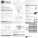
Connect the blue neutral wire to the terminal marked “N.”
Connect the brown line wire to the terminal marked “L.”
Note: An additional “L” terminal is provided for separate control of the light xture. This terminal is not
required for controlling the light xture with the remote control.
Note: If there is no separate line for the light kit, connect the black/white wire and the brown wire from
the motor housing to the same “L” terminal.
Feed the electrical connector from the fan through the hole in the hanger bracket so it is on the outside
of the hanger bracket.
The remote receiver is connected between the electrical connector coming from the fan and the electrical
connector coming from the hanger bracket terminal block. See Figure 2.
Slide the remote receiver through the two rectangular openings in the hanger bracket and center it in
the hanger bracket, as shown in Figure 4.
The male connector on the remote receiver attaches to the female connector on the fan. The female
connector on the remote receiver attaches to the male connector on the hanger bracket. They are
keyed so they will only connect one way. See Figure 2.
Do not force the connectors. To aid in proper connection, align the color code stickers on each connector
so they are in line with each other then press them together until they lock.
CAUTION: Be sure no bare wire or wire strands are visible after making connections.
Make sure none of the wires are caught in any of the hanging assembly components. The white
antenna wire should be extended to its full length and positioned between the hanger bracket
and the canopy parts upon nal assembly.
Once the receiver is installed, continue with the appropriate instructions from the fan installation manual
to nish installing the fan.
Testing the Control
Warning! - Do not use the light xture pull chain to operate the light while power is
applied to the receiver as damage could occur to the receiver. It is recommended to shorten the
pull chain(s) to prevent accidental use.
• Do not use the fan pull chain switch to operate the fan speeds while power is applied to the
receiver as damage could occur to the receiver.
Remote Ceiling Fan & Light Control
Transmitter Model: 24756
Part Number: 87261-01
Transmitter Battery: 12V, Type A23, MN-21 or equivalent
Receiver Part Number: 87262-01
Ratings: 240 VAC, 50/60Hz, 1.0 Amp Fan
Receiver Weight: 160g
Max 300 Watts Incandescent or Halogen Light
Read and Save these Instructions
WARNING! Risk of Electrical Shock
• To avoid possible electrical shock, before wiring fan, disconnect power by turning off the power
mains both to the outlet box and to its associated wall switch location.
Compliance
• This equipment has been tested and complies with: EN 300220:2002 and EN 55022:1998 Class
B.
• All wiring must be in accordance with national and local electrical codes. If you are unfamiliar
with wiring, you should use a qualied serviceman.
• In Australia, national laws require a qualied electrician to install this accessory into a ceiling
fan.
• To avoid overheating and possible damage to other equipment, do not install to control
a receptacle, uorescent light xture, motor-operated appliance, or transformer-supplied
appliance.
• Use only to control one paddle-blade ceiling fan and incandescent or halogen light xture.
Note: Any changes or modications to the transmitter or receiver not expressly approved by Hunter
Fan Company may void one’s authority to operate this remote control.
For use only with electrically reversible ceiling fans rated at 1.0 A or less, and fan incandescent light
kits rated at 300 W or less.
If this equipment does cause harmful interference to radio or television reception, which can be determined
by turning the equipment off and on, the user is encouraged to try to correct the interference by one or
more of the following measures:
• Reorient or relocate the receiving antenna.
• Increase the separation between the equipment and receiver.
• Connect the equipment into an outlet on a circuit different from that to which the receiver is
connected.
• Consult the dealer or an experienced radio/TV technician for help.
Installing the Receiver
Disconnect the power mains to the ceiling fan and light kit at the main electric panel. Remove fuse or
move circuit breaker to the OFF position. Turn off wall switch.
IMPORTANT! Before installing this control, change the factory default jumper / DIP switch settings
to your own unique code. The jumpers are under the battery compartment of the remote and the DIP
switches are on the at side of the receiver. Refer to Figure 1. Remove the battery from the remote
and turn off power to the fan when making any jumper / DIP switch setting changes.
Figure 1 - Setting Receiver DIP Switches and Remove Jumpers
A jumper that connects the two pins is equivalent to a DIP switch being set to the ON position. A jumper
stored on a single pin is the same as a DIP switch set in the OFF position.
Be sure the jumper settings of the transmitter and receiver match, or the ceiling fan will not function.
Select different combinations of jumoer / DIP switch settings to prevent miss operation due to other
remote control fans, garage door openers, etc.
Note: The jumpers on the transmitter read from right to left 4-1, and the DIP swiches on the receiver
read from left to right, 1-4. Be sure to match the settings by number rather than by their right to left
positions.
Install one type A23, MN-21 or equivalent, 12 volt alkaline battery inside the hand-held transmitter after
setting the ON / OFF jumper settings on the remote to match the ON / OFF DIP switch settings on the
receiver. Refer to Figure 1.
Install the ceiling fan according to its instructions, up to the point of making the electrical connections.
Connecting Fan to Electrical Source
Use Figures 2 and 3, for reference in making the following electrical connections.
Connect the supply mains to the terminal block mounted on the hanger bracket.
Connect the safety earth (green/yellow) wire to the terminal marked .
When the installation is complete and while there is no power (your wall switch is in the OFF position)
to the receiver, pull the light kit’s pull chain once and pull the fan speed pull chain once.
Turn on the wall switch. The light kit should turn ON. If the light remains OFF, turn off the power at the
wall switch. Pull the light kit’s pull chain to turn the light ON.
Turn the wall switch back ON.
Press the remote control’s fan speed button. The fan should start and reach it’s maximum speed. If the
fan does not start or is turning too slow, turn off the power at the wall switch. Pull the fan’s pull chain to
change speed. Reapply power and try HIGH.
Hunter Fan Company
2500 Frisco Avenue
Memphis TN 38114 USA
© 2006 Hunter Fan Company
41612-01 10/12/06
Hunter Fan
Company
Figure 3 - Terminal Block Connections
Possible Causes
Main Power not restored.
Fan pull chain not set to HIGH.
Light pull chain not set to ON.
Receiver wiring incorrect.
Transmitter and receiver DIP
switches do not match.
Battery too weak.
Signal blocked from reaching
receiver.
Solution
2. Operates only at
close range.
Symptom
3. Inconsistent operation.
Replace fuse. Turn ON supply mains.
Turn ON wall switch.
Turn OFF power at wall switch or
main supply mains. Set fan to HIGH
speed.
Set light kit to ON.
Verify wiring connections.
Set transmitter and receiver to same
DIP switch setting.
Replace with new, alkaline battery.
Extend antenna into wire into ceiling
box, or move it for better reception.
1. No functions operate.
Battery too weak.
Signal partially blocked from
reaching receiver.
RF interference.
Continuing RF interference.
Replace with new, alkaline battery.
Extend antenna into ceiling box, or
move it for better reception.
Turn OFF wall switch for 5 seconds,
then turn back ON.
Change dip switch settings to a
different code in both Transmitter
and Receiver.
Troubleshooting
Figure 2 - Wiring Diagram
Remote
Receiver
Hanger
Bracket
Figure 4 - Remote Receiver in Hanger Bracket
Operation
Turn ON the wall switch, the light will turn ON at maximum brightness and the fan will be off.
Light Operation
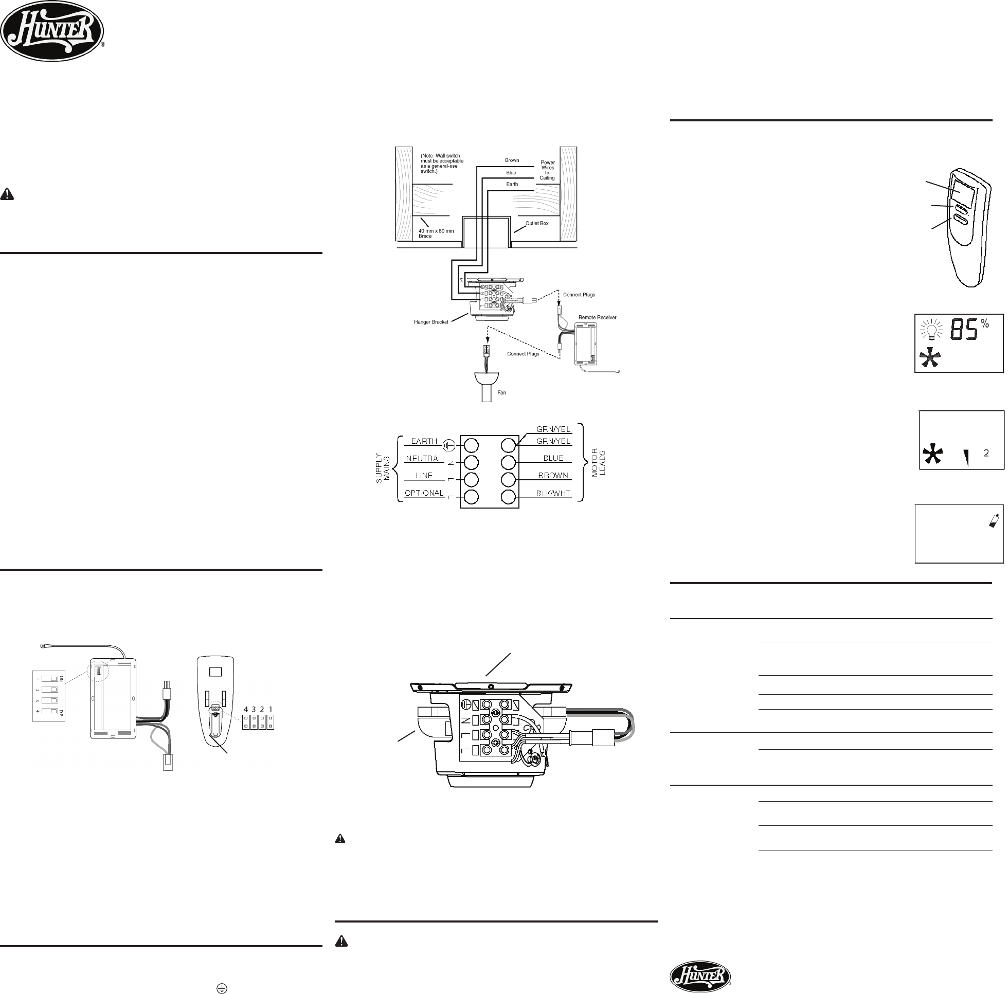
• ON and OFF: Press and quickly release the light button on the
hand-held remote to turn the light OFF and ON. See Figure 5 for
remote button locations.
Dimmer
Press and hold the light button for more than one second to dim or brighten
the light. If brightness is initially at 100%, then the brightness will decrease
to 95% and so forth by 5% increments as long as the light button is pressed.
When the minimum brightness of 25% is reached, the setting will pause
and then begin to increase by 5% increments as long as the light button
is pressed. See Figure 6.
Fan Operation
• ON, OFF, and Speed Setting: Press the fan button to turn on the ceiling fan
at HIGH speed. Press again to change the speed to MEDIUM, then again
to LOW, and then again to turn the fan OFF. See Figure 7.
To reverse the fan direction, turn the fan off and wait for the blades to stop
moving. Switch the reversing switch on the fan to the opposite direction.
Restart fan.
Low Battery Detection
• The low-battery icon will ash when the battery needs to be changed. If
there is a low battery, it will also ah during standby mode.
• Replace the battery when the low-battery warning begins to ash as
shown in Figure 8.
Standby Mode
• To save battery power, if no button on the remote is pressed for one
minute, the remote LCD will go into standby mode.
• During standby mode, all LCD icons are turned off.
• The LCD will will resume original display when any button is pressed.
The button function is not performed but acts as a wake up key.
Receiver
Remote
DIP Switches
Jumpers
Battery Compartment
Figure 6
Figure 8
Figure 7
LCD Display
Light
Fan
Figure 5