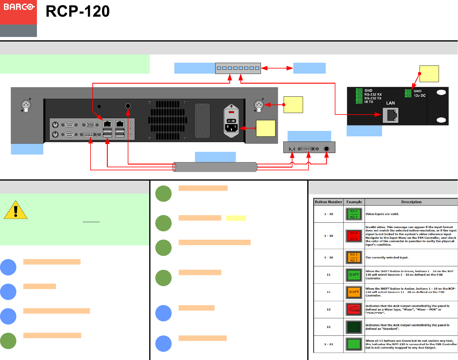
Understanding Button Color
For detailed installation instructions, refer to Chapter 2 of
the RCP-120 User’s Guide.
Touch Screen
Connector Panel
USB DVI-D 12V DC
Script
Light
RCP-120 Rear
Panel
FSN-150 Rear
Panel
Ethernet Switch
RCP-120 Setup
Quick Start Guide
Visibly yours
Barco, Inc.
11101 Trade Center Drive
Rancho Cordova, CA
95670 • USA
P/N 26-1004005-00, Rev 00
General FSN System Setup — Follow the steps outlined in
Chapter 6 of the FSN User’s Guide to setup the FSN System
before connecting the RCP-120 devices.
1
FSN Aux Setup — Refer to Aux Setup in Chapter 6 of the
FSN User’s Guide to configure the Aux Outputs on the FSN
system.
2
3
4
5
6
7
8
RCP-120 setup is comprised of 10 sequences,
each of which includes several steps.
For error-free setup, always refer to either the
FSN User’s Guide, indicated by the blue circles or the
RCP-120 Users Guide, indicated by the green circles.
Assign Aux Outputs — On the Assign Remote Panels Menu,
select the appropriate RCP-120 panel and press the {Assign
Aux} button. In the Select Aux Output Pop-up that appears,
select the Aux Output that will be controlled by this RCP-120.
Repeat this step for any additional devices. When finished,
press the {Close} button to clear the pop-up.
RCP-120 Installation: System Connections
Toll Free:
Fax:
Technical Support:
Website:
+1 (888) 414-7226
+1 (916) 859-2515
+1 (866) 374-7878
www.barco.com
Verify Aux Output Configuration — Ensure the Aux Outputs
are working as expected by following the steps outlined in the
Working with Aux Buses section in Chapter 7 of the FSN
User’s Guide.
Install the RCP-120 Devices — Use a standard Ethernet
cable to connect the LAN port on the RCP-120 to the
Ethernet switch used to connect the FSN-1400 and Ethernet
Port 1 of the FSN Controller.
Communications Setup — Make sure each RCP-120 has a
unique IP Address, compatible with the FSN network. Use a
computer attached to the same network to browse to the RCP-
120 Web Interface and change the IP Address if necessary.
Refer to Chapter 3 in the RCP-120 User’s Guide.
Remote Panel Name — (Optional) Give the RCP-120 a
unique name. Browse to the RCP-120 Web Interface and
update the Host Name to uniquely identify each panel. Refer
to Chapter 3 in the RCP-120 User’s Guide.
Setup Panels in the FSN Controller — On the Assign
Remote Panels Menu, under the System, Other Setup Menu,
press {Discover Remote Panels} to search the FSN network
and populate the Remote Panel Table. Refer to Chapter 4 in
the RCP-120 User’s Guide.
12V DC OUT
1.5A
Ethernet
Port 2
Ethernet
Port 1
Cable Harness
DC
Power
To FSN-1400
9
Saving the Setup — On the System Menu, press {Save All} to
save all system parameters to non-volatile memory, including
input and output setups, button mappings, tallies, user
preferences and more. Refer to Chapter 6 in the FSN User’s
Guide.
Backing up the System — Insert a USB drive into the USB
Port. On the Backup and Restore Menu, press {Backup
System} to back up the system setup and all memory registers.
Refer to Chapter 6 in the FSN User’s Guide.
10
AC
Power


